

TOC (ASCE/SEI 19-16)
Provisions
CommentaryCLAMPS
The recommended groove diameter of clamps shall be the nominal diameter of the cable plus positive tolerances. Table C-1 provides recommended tolerances in fractional dimensions. These are generally in the range of +3% min to +11% max compared with the cable diameter.
| Wire Ropes | Strands | ||||
|---|---|---|---|---|---|
| Tolerance (in.) | Tolerance (in.) | ||||
| Wire Rope Diameter (in.) | Min. | Max. | Strand Diameter (in.) | Min. | Max. |
| 3/8 to 1-1/8 | +1/32 | +3/32 | 1/2 to 1-1/2 | +1/32 | +3/32 |
| 1-3/16 to 1-1/2 | +1/16 | +1/8 | 1-9/16 to 2-1/2 | +1/16 | +1/8 |
| 1-9/16 to 2-1/8 | +3/32 | +5/32 | More than 2-1/2 | +1/8 | +3/16 |
| 2-3/16 to 3 | +1/8 | +3/16 | |||
| More than 3 | +5/32 | +1/4 | |||
Note: 1 in. = 25.4 mm.
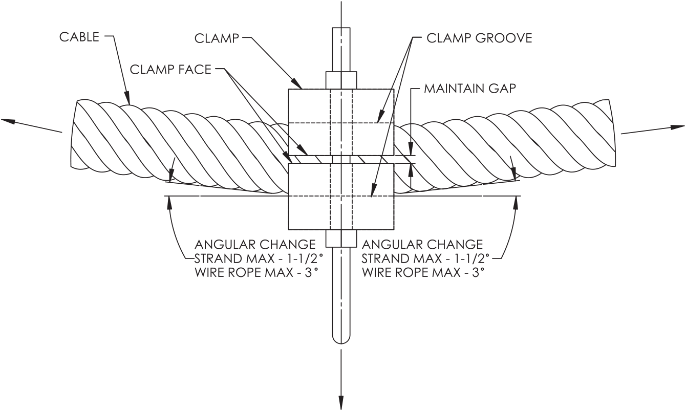
The depth of the groove in the clamps shall be such that when the clamps are fully tightened their faces will not be in contact with each other.
The maximum design coefficient of friction recommended to prevent slipping of the clamps on the strand or rope shall be 10%.
The recommended maximum allowable projected bearing pressure exerted on the strand or rope by the clamp should be 4,000 psi (27.6 MPa) for 3-in. (76-mm) size and larger, increasing linearly to 6,000 psi (41.4 MPa) for 1-in. (25-mm) size.
Cast clamps shall have a smooth surface in the grooves. All rough and high spots shall be removed.
All edges that contact the strand or wire rope shall be sufficiently rounded to suit all conditions of design and erection.
The nuts on the bolts of the clamps shall be alternately and gradually tightened to avoid any excessive unequal stressing of the clamp components or the cable to which the clamp is being attached.
The recommended angular change in direction of the cable at a clamp of the type shown in Figure C-1 shall not exceed 1.5 deg for strand or 3 deg for wire rope.
Commentary
CLAMPS
There is no commentary for Appendix C.