

TOC (ASCE/SEI 7-16)
Provisions
CommentaryBuildings Exempted from Torsional Wind Load Cases
Building structures are exempted that are regular under seismic load (as defined in Section 12.3.2) and conform to the following:
- 1.
The eccentricity between the center of mass and the geometric centroid of the building at that level shall not exceed 15% of the overall building width along each principal axis considered at each level, and
- 2.
The design story shear determined for earthquake load as specified in Chapter 12 at each floor level shall be at least 1.5 times the design story shear determined for wind loads as specified herein.
The design earthquake and wind load cases considered when evaluating this exception shall be the load cases without torsion.
Building structures are exempted that are regular under seismic load (as defined in Section 12.3.2) and conform to the following:
- 1.
The design earthquake shear forces resolved to the vertical elements of the lateral load-resisting system shall be at least 1.5 times the corresponding design wind shear forces resisted by those elements.
The design earthquake and wind load cases considered when evaluating this exception shall be the load cases without torsion.
Buildings meeting the definition of torsionally regular buildings under wind load contained in Section 26.2 are exempted.
EXCEPTION: If a building does not qualify as being torsionally regular under wind load, it is permissible to base the design on the basic wind load Case 1 that is proportionally increased so that the maximum displacement at each level is not less than the maximum displacement for the torsional load Case 2.
D.6 Class 1 and Class 2 Simple Diaphragm Buildings h ≤ 160 ft ( 48.8 m ) Meeting the Following Requirements (Refer to Section 27.5.2)
Square buildings with are exempted, where all the following conditions are satisfied:
- 1.
The combined stiffness of the MWFRS in each principal axis direction shall be equal, and
- 2.
The individual stiffness of each MWFRS in each principal axis direction shall be equal and symmetrically placed about the center of application of the wind load along the principal axis under consideration, and
- 3.
The combined stiffness of the two most separated lines of the MWFRS in each principal axis direction shall be 100% of the total stiffness in each principal axis direction, and
- 4.
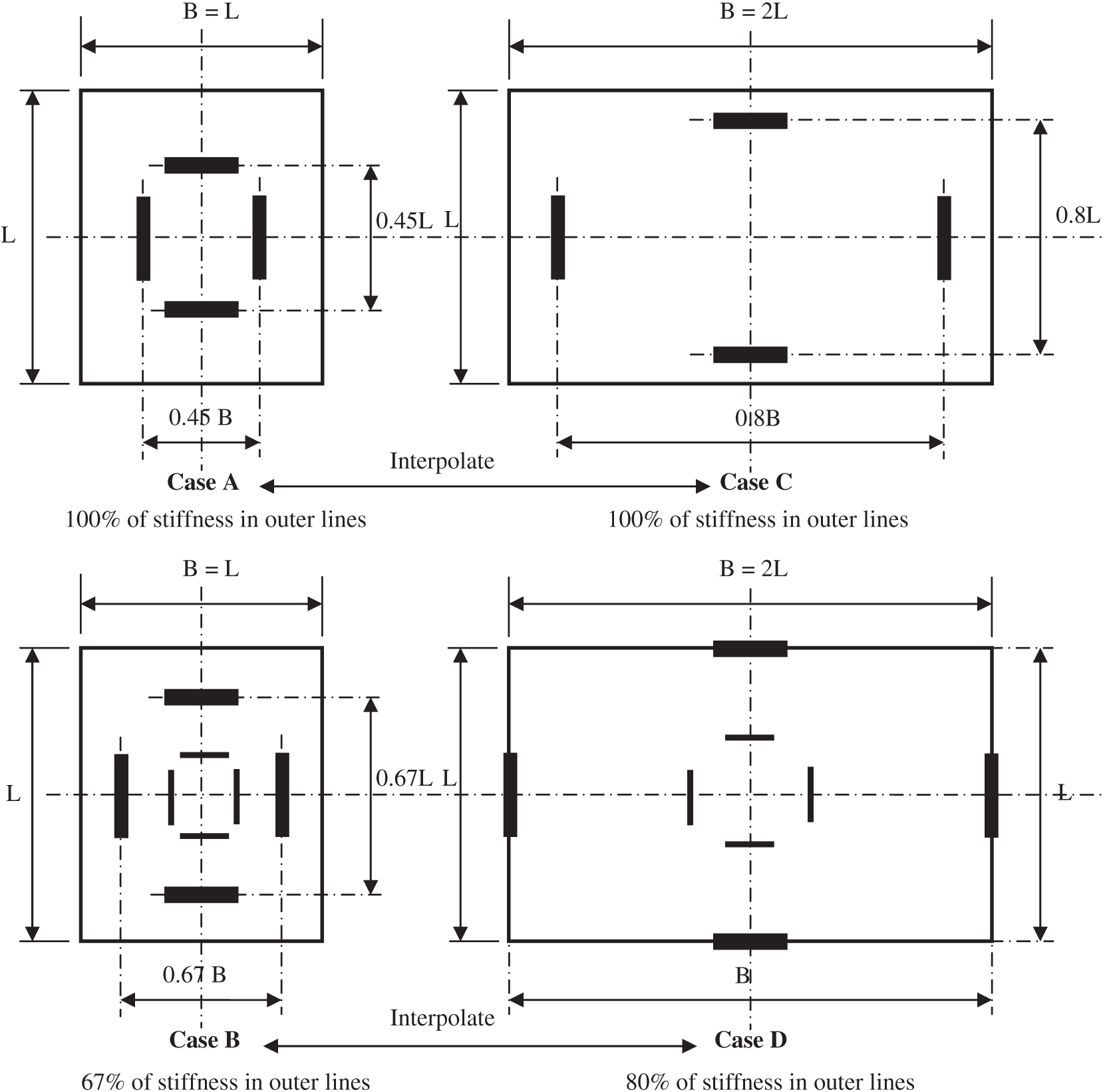
The distance between the two most separated lines of the MWFRS in each principal axis direction shall be at least 45% of the effective building width perpendicular to the axis under consideration.
Square buildings with are exempted, where all the following conditions are satisfied:
- 1.
The combined stiffness of the MWFRS in each principal axis direction shall be equal, and
- 2.
The individual stiffness of the two most separated lines of the MWFRS in each principal axis direction shall be equal with all lines of the MWFRS symmetrically placed about the center of application of the wind load along the principal axis under consideration, and
- 3.
The combined stiffness of the two most separated lines of the MWFRS in each principal axis direction shall be at least 66% of the total stiffness in each principal axis direction, and
- 4.
The distance between the two most separated lines of the MWFRS in each principal axis direction shall be at least 66% of the effective building width perpendicular to the axis under consideration.
Rectangular buildings with equal to 0.5 or 2.0 ( , ) are exempted, where all the following conditions are satisfied:
- 1.
The combined stiffness of the MWFRS in each principal axis direction shall be proportional to the width of the sides perpendicular to the axis under consideration, and
- 2.
The individual stiffness of each of the MWFRS in each principal axis direction shall be equal and symmetrically placed about the center of application of the wind load along the principal axis under consideration, and
- 3.
The combined stiffness of the two most separated lines of the MWFRS in each principal axis direction shall be 100% of the total stiffness in each principal axis direction, and
- 4.
The distance between the two most separated lines of the MWFRS in each principal axis direction shall be at least 80% of the effective building width perpendicular to the axis under consideration.
Rectangular buildings with equal to 0.5 or 2.0 ( , ) are exempted, where all the following conditions are satisfied:
- 1.
The combined stiffness of the MWFRS in each principal axis direction shall be proportional to the width of the sides perpendicular to the axis under consideration, and
- 2.
The individual stiffness of the most separated lines of the MWFRS in each principal axis direction shall be equal with all lines of the MWFRS symmetrically placed about the center of application of the wind load along the principal axis under consideration, and
- 3.
The combined stiffness of the two most separated lines of the MWFRS in each principal axis direction shall be at least 80% of the total stiffness in each principal axis direction, and
- 4.
The distance between the two most separated lines of the MWFRS in each principal axis direction shall be 100% of the effective building width perpendicular to the axis under consideration.
Rectangular buildings having between 0.5 and 1.0 ( ) or between 1.0 and 2.0 ( ), the stiffness requirements and the separation distances between the two most separated lines of the MWFRS in each direction shall be interpolated between Case A and Case C and between Case B and Case D, respectively (Fig. D.6-1).
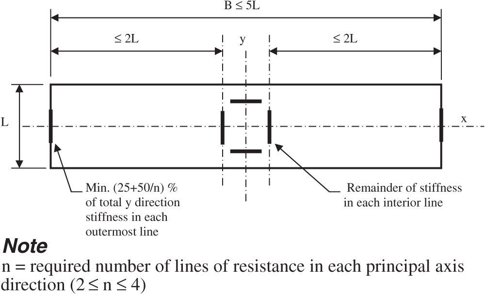
Rectangular buildings having between 0.5 and 0.2 ( ) or between 2.0 and 5.0 ( ) are exempted, see Fig. D.6-2, where all of the following conditions are satisfied:
- 1.
There shall be at least two lines of resistance in each principal axis direction, and
- 2.
All lines of the MWFRS shall be symmetrically placed about the center of application of the wind load along the principal axis under consideration, and
- 3.
The distance between each line of resistance of the MWFRS in the principal axis direction shall not exceed 2 times the least effective building width in a principal axis direction, and
- 4.
The individual stiffness of the most separated lines of the MWFRS in each principal axis direction shall be equal and not less than ( ) percent of the total stiffness where is the required number of lines of resistance in the principal axis direction as required by conditions 1 and 3 of this section. The value of shall be 2, 3, or 4.
Commentary
Buildings Exempted from Torsional Wind Load Cases
As discussed in Section C27.3.6, a building will experience torsional loads caused by nonuniform pressures on different faces of the building. Because of these torsional loads, the four load cases as defined in Fig. 27.3-8 must be investigated except for buildings with flexible diaphragms and for buildings with diaphragms that are not flexible meeting the requirements for spatial distribution and stiffness of the main wind force resisting system (MWFRS).
The requirements for spatial distribution and stiffness of the MWFRS for the simple cases shown are necessary to ensure that wind torsion does not control the design. Presented in Appendix D are different requirements which, if met by a building’s MWFRS, then torsional wind load cases need not be investigated. Many other configurations are also possible, but it becomes too complex to describe their limitations in a simple way.
In general, the designer should place and proportion the vertical elements of the MWFRS in each direction so that the center of pressure from wind forces at each story is located near the center of rigidity of the MWFRS, thereby minimizing the inherent torsion from wind on the building. In buildings with rigid diaphragms, a torsional eccentricity larger than about 5% of the building width should be avoided to prevent large shear forces from wind torsion effects and to avoid torsional story drift that can damage interior walls and cladding.
The following information is provided to aid designers in determining whether the torsional wind loading cases (Fig. 27.3-8, load cases 2 and 4) control the design. Reference is made to Fig. CD-1. The equations shown in the figure for the general case of a square or rectangular building having inherent eccentricity or about principal axis 1 and 2, respectively, can be used to determine the required stiffness and location of the MWFRS in each principal axis direction.
Using the equations contained in Fig. CD-1, it can be shown that regular buildings (as defined in Chapter 12, Section 12.3.2), which at each story meet the requirements specified for the eccentricity between the center of mass (or alternatively, center of rigidity) and the geometric center with the specified ratio of seismic to wind design story shears can safely be exempted from the wind torsion load cases of Fig. 27.3-6. It is conservative to measure the eccentricity from the center of mass to the geometric center rather than from the center of rigidity to the geometric center. Buildings that have an inherent eccentricity between the center of mass and center of rigidity and that are designed for code seismic forces have a higher torsional resistance than if the center of mass and rigidity are coincident.
Using the equations contained in Fig. CD-1 and a building drift analysis to determine the maximum displacement at any story, it can be shown that buildings with diaphragms that are not flexible and that are defined as torsionally regular under wind load need not be designed for the torsional load cases of Fig. 27.3-6. Furthermore, it is permissible to increase the basic wind load case proportionally so that the maximum displacement at any story is not less than the maximum displacement under the torsional load case. The building can then be designed for the increased basic loading case without the need for considering the torsional load cases.