

TOC (ASCE/SEI 19-16)
Provisions
CommentarySMALL DIAMETER CABLE FOR EARTHQUAKE RESISTANCE
This appendix contains requirements for the structural design, contract documents, shop drawings, fabrication, and installation of cable less than 3/8 in. in diameter used for the purpose of providing earthquake load resistance (such as sway bracing) of nonstructural architectural, mechanical, and electrical components of buildings.
Anchorage—The structural connection at which the cable is terminated
Cable—A flexible tension member, either strand or rope
Damper—An active or passive device attached to the cable structure that reduces vibration amplitudes by removing energy from the vibrating cable to modify the structural response to dynamic loads
End Fitting—Fitting used to attach the cable to the structure or component
Grade—Classification of cable by nominal cable strength and/or metallic composition of wire
Intermediate Fitting—Fitting between end fittings within the length of the cable
Minimum Breaking Force—Minimum strength of a cable in units of force, as listed in the appropriate ASTM or other applicable standards
Modulus of Elasticity—The slope of the secant to the stress-strain curve between the stress at 10% of the nominal cable strength and 90% of the prestretching force (see Fig. 1-1 in the main standard)
Prestretching—Tensioning a cable according to a predetermined program to minimize constructional (in-service) stretch
Prestretching Force—Tensile force applied to a cable one or more times and held for a specified duration during prestretching
Rope—A plurality of strands twisted about an axis
Strand—A plurality of wires helically twisted about an axis
Wire—A single, continuous length of steel with a circular cross section; wires of circular cross section are cold-drawn from rod
For each type of cable in the proposed earthquake load resisting system, the contract specifications shall indicate the diameter (size), type of cable, wire coating, grade of cable, and applicable material or testing specification. If additional design requirements for cables exist, they shall be included in the contract specifications. The contract specifications shall identify all other required submittals, including shop drawings and test reports.
Shop drawings for the fabrication of cables and fittings shall reflect the requirements indicated in the contract documents. Exact locations, material, sizes, and dimensions of all cables and fittings shall be shown, as well as fabricating and preparation procedures for cables and fittings. Where approved substitutions or changes from the contract documents are made, an alternate member or fitting shall be detailed that will satisfy the loading and configurations indicated in the contract documents.
Shop drawings and required test reports shall be submitted to the engineer for review.
The required strength, Sr, of each cable assembly shall be equal to the value of T given in Section E3.2.2.
The allowable strength, Sa, of the cable assembly shall be taken as
in which
Smin = minimum breaking force
Ω = safety factor =2.2
The possibility of elevated temperature above 200 °F (93 °C) and its effect on the mechanical and physical properties of cables and end fittings shall be considered during the design. For temperatures above 200 °F (93 °C), the nominal cable strength, Sn, and the cable’s modulus of elasticity, Es, shall be reduced appropriately in calculations.
Fitting and cable assemblies shall develop an ultimate strength greater than the minimum breaking force prescribed by the materials specifications identified in Section E4.1. Moreover, fittings shall be designed such that when a fitting and cable assembly is tested in its installed configuration, the tested strength of the assembly exceeds the specified minimum breaking force of the cable. Further, during the test, the cable shall not break within the fitting(s).
The earthquake loads that are required to be resisted by sway braces for nonstructural building components are prescribed by the provisions of ASCE/SEI 7-10, “Minimum design loads for buildings and other structures.” The general and special requirements of Chapter 13 of ASCE/SEI 7-10 shall be taken into account in the design and installation of cable assemblies used for earthquake load resistance of nonstructural building components.
This appendix to the standard applies to cables conforming to the following standard specifications:
ASTM A368-95a (2013), “Standard specification for stainless steel wire strand.”
ASTM A492-95 (2013), “Standard specification for stainless steel rope wire.”
ASTM A1023/A1023M-15, “Standard specification for carbon steel wire ropes for general purposes,” Table 7.
Some of the aforementioned cable specifications apply to cables of a specific construction. This standard does not exclude cables of other construction provided that the chemical and mechanical properties of the wires constituting the cables conform to the requirements of one of the cable specifications and provided that the cables do not have nonmetallic (fiber) cores.
For each type and construction of cable specified in the contract documents, any prestretching requirements shall be explicitly stated. For prestretched cables, the minimum value of the modulus of elasticity, Es, of the cable after prestretching shall be specified. Prestretching force shall not exceed 60% of the minimum breaking force.
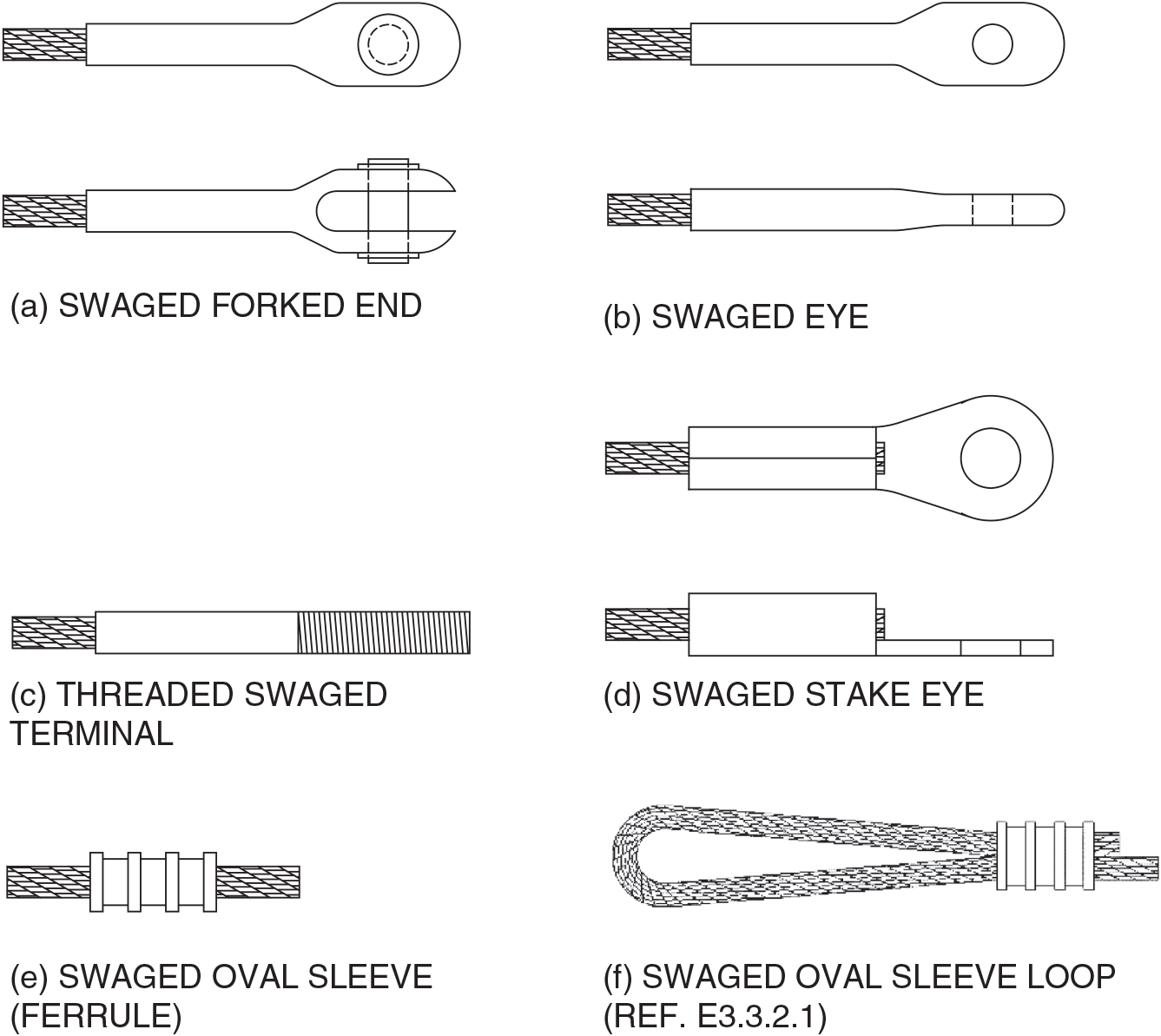
End and intermediate fittings should be accessible and positioned so as not to create a collection basin for dirt or moisture. Examples of representative end fittings are contained in Fig. E-1.
Except for cables composed of stainless-steel wires, cables shall be coated with zinc (galvanized) in accordance with applicable zinc coating provisions of ASTM A1023-09 or another standard approved by the engineer.
In addition to previously cited specifications, the following specifications apply to corrosion and fire protective coatings:
ASCE/SEI/SFPE 29-05, “Standard calculation methods for structural fire protection.”
ANSI/UL 263 (2011), “Standard for fire tests of building construction and materials.”
ASTM A780/A780M-09 (2015), “Standard practice for repair of damaged and uncoated areas of hot-dip galvanized coatings.”
ASTM B6-13, “Standard specification for zinc.”
ASTM E119-15, “Standard test methods for fire tests of building construction and materials.”
Basic corrosion protection shall be provided for all cable systems. At a minimum, each individual carbon steel cable wire, exclusive of stainless steel wires, shall be galvanized with zinc or a zinc-aluminum-mischmetal alloy. The in-service exposure of the cable shall be considered when specifying the required galvanizing thickness.
Cable end fittings shall be galvanized or zinc-metalized and shall be stainless steel for stainless-steel cables.
Cable and fitting assemblies shall be tested to meet the criteria in Section E3.3.2 prior to their installation. Listing and labeling by a nationally recognized third-party organization not directly affiliated with the manufacturer of the cable or fittings shall be considered acceptable testing.
Cables shall be prestretched to achieve the minimum modulus of elasticity values specified for the product. Prestretching is optional for ASTM A1023, Table 7, cables that are ¼ in. or less in diameter and meet or exceed the minimum modulus of elasticity (Es) value of 17.5 × 10⁶ psi, when tested in accordance with the test procedures in Section E7.3.1.
E7.3.1 Test Method for Determining Modulus of Elasticity (Young’s Modulus) for Cables with Diameters 1/4 in. and Smaller In Lieu of Prestretching.
The test shall be performed with a minimum cable specimen length of 50 in. and a minimum effective gauge length of 30 in.
Test Method (Reference Fig. 1-1 of the Standard)
- 1.
Load the specimen to 10% of the minimum breaking force (MBF) of the cable and hold for 1 min.
- 2.
Gradually increase the load to 55% of the MBF of the cable and hold for 1 min. The load shall be applied in no less than 5 s and no more than 10 s.
- 3.
Smoothly reduce the load to 10% of the MBF of the cable in no less than 3 s and no more than 10 s and hold at 10%.
- 4.
Zero the length gauge while the specimen is under the load of 10% of the MBF of the cable.
- 5.
Gradually increase the load to 55% of the MBF of the cable and hold for 1 min. The load shall be applied in no less than 5 s and no more than 10 s.
- 6.
Measure the extension of the gauge length under load of 55% of the MBF of the cable.
- 7.
Calculate the modulus of elasticity (Es) based on the cross-sectional area of the cable using the formula for Young’s Modulus as shown:
where
Es
Young’s Modulus (modulus of elasticity)
F
tensile force range exerted on the cable between extension gauge length measurements = forece at 55% of MBF – force at 10% MBF
A0
the original cross-sectional area through which the force is applied (aggregate cross-sectional area of the wires in the cable)
ΔL
the amount by which the length of the specimen changes
L0
the original length of the specimen
Cable assemblies shall be shipped on reels or in coils. Prestretched cable shall not be wound onto a reel or into a coil that has a diameter less than 50 times the cable diameter. Nonprestretched cable shall not be wound onto a reel or into a coil that has a diameter less than 25 times the cable diameter. Both wire diameter and cable prestretch influence cable flexibility. Smaller reel or coil diameters shall be approved only after consultation with cable manufacturers and acceptance of their shipping practices. Utmost care shall be exercised during shipment and handling to avoid damage to the cables and their coatings. Shipments shall be accompanied by a certificate attesting to the breaking strength of the cable assemblies, details of installation, and tools related to the installation and special installation precautions, if any, to ensure proper installation.
An emergency inspection is an unscheduled inspection to assess structural damage resulting from earthquakes, human actions, or fire exposure.
The intent of the emergency inspection is to determine the extent of repairs that may be necessary for the bracing cables of nonstructural components. This inspection is independent from any inspection of the components themselves.
Commentary
SMALL DIAMETER CABLE FOR EARTHQUAKE RESISTANCE
CE1.0 GENERAL
The 2010 edition of this standard recognizes the use of cable less than 3/8 in. in diameter for the purpose of providing earthquake load resistant sway bracing of nonstructural architectural, electrical, and mechanical components of buildings by inserting ASTM A1023 Standard Specifications for Carbon Steel Wire Ropes for General Purposes, Table 7, into Section 4.1 of the standard and also referencing the application as described in the commentary. Because various provisions of the standard do not apply or fully apply to this type of use for small diameter cable, stand-alone requirements have now been set forth in Appendix E. It is reemphasized here that the requirements set forth in this appendix are for cable that is used solely for the purpose of providing earthquake load resistance (such as sway bracing) of nonstructural architectural, electrical, and mechanical components of buildings. These small diameter cables resist no other loads.
CE1.1 GLOSSARY
Some manufacturers and some ASTM specifications refer to minimum breaking force as “nominal cable strength” or “minimum breaking strength.”
Prestretching is generally a shop operation performed before a cable is shipped. Prestretching normally is conducted without first having the fittings installed. Prestretching is not a mandatory requirement in Appendix E.
CE3.0 DESIGN CONSIDERATIONS
CE3.1 DESIGN BASIS
The design basis normally is determined by the provisions of Chapter 13 of ASCE 7-10 as referenced by the codes of the federal, state, or local authority having jurisdiction. Resistance to those forces needs to be observed. The formulas for loads and resistance identified in this appendix generally are considered as allowable stress design (ASD) criteria.
CE3.2 DESIGN LOADINGS
CE3.2.1 Loads.
The earthquake loads that are required to be resisted are prescribed by the provisions of ASCE 7-10 as generally referred to by federal, state, and local building codes.
CE3.2.2 Load Combinations.
The load combinations adopted for this appendix are the same as the basic combinations for allowable stress design (ASD) in ASCE/SEI 7-10 as prescribed for earthquake loads. Because this appendix is intended to address the use of cable that is less than 3/8 in. in diameter used for earthquake load resistance (such as sway bracing) of nonstructural architectural, mechanical, and electrical building components, no other loads are intended to be supported by such sway bracing assemblies. In addition, these cable assemblies are never prestressed.
CE3.3 CABLE AND FITTING ASSEMBLY STRENGTH
CE3.3.1.1 Elevated Temperature Effect
The physical strength and other mechanical properties of cable materials that are exposed to an ambient temperature of 200 °F (93 °C) for extended periods of time are of concern. The physical strength and other mechanical properties of cable materials in fires also can be a critical concern. This critical concern generally relates to federal, state, or local codes and their provisions concerning the extent that cable support assemblies will be required to have a fire-resistant rating because of the height, area, and use of a building. See also Section E6.2.
CE3.3.2.1 Cable Loop Connections
It is commonplace for manufacturers of cable type seismic sway brace components to design and manufacture special intermediate fittings or connections to braced, nonstructural building components, the shape of which does not permit the installation of a thimble. However, their use has been accepted industry and/or engineering practice for many years when they are routinely tested as described in Section E7.2.
CE5.0 FITTINGS
The 2010 edition of the standard eliminates cable clips and wedge type end fittings, principally because these fittings tended to loosen with time and/or damage the cable, thereby compromising the requirement that the cable assembly be capable of developing a strength greater than the specified minimum breaking force. This, in turn, meant that swaged fittings are the only practical fittings for earthquake sway bracing assemblies. Virtually all fittings used in earthquake sway bracing assemblies are “off-the-shelf” item fittings that are designed to allow for variable length adjustments at one end or the other when the sway bracing is installed. Consequently, properly calibrated hand swaging tools are necessary for proper field installation. See also Section E8.
CE5.3 END FITTINGS AND INTERMEDIATE FITTINGS
See Fig. E-1.
CE6.0 PROTECTIVE COATINGS
ASTM A1023/A1023M-15, Standard Specification for Stranded Carbon Steel Wire Ropes for General Purposes, does not specify a class of zinc coating. It requires a minimum coating weight, which varies based on the diameter of the wires in the cable.
For exposures involving condensation, salt, or chemicals, stainless steel may be required.
CE7.0 FABRICATION, SHIPPING, AND RECEIVING
The term “fabrication” as used in this appendix signifies manufacturing operations, such as prestretching, measuring, cutting, swaging, testing of cable and fitting assemblies, and reeling or coiling cables.
CE7.2 TESTING OF CABLE AND FITTING ASSEMBLIES
The “Testing of Cable and Fitting Assemblies” provisions of this appendix reflect and recognize the acceptability of construction industry practice to use third-party testing, inspection, and listing of products related to compliance with codes and material standards requirements. The ICC-ES and Underwriters Laboratories provide product testing and listing for steel cable and fitting assemblies used for seismic sway bracing. This listing system provides reasonable assurance that a manufacturer is supplying products that have been constructed to specified materials standards and tested to meet codes and standards.
CE7.3 PRESTRETCHING
Elongation of a cable subjected to tension results from a combination of elastic or recoverable stretch of the wire material and inelastic or constructional stretch. The latter results from the equipment utilized in manufacturing the cable, arrangement of the wires within the cable, and length of lay (helical pitch) of the cable components. To minimize the effect of constructional stretch, the cable may be prestretched by applying a predetermined tension not exceeding 60% of the minimum breaking force of the cable. After prestretching, the cable has better defined and more uniform elastic properties.
CE9.0 POST-CONSTRUCTION CONSIDERATIONS AND INSPECTION
CE9.1 EMERGENCY INSPECTIONS
Emergency inspections are performed after the cable system experiences sudden damage due to environmental factors (earthquake overloads), human interactions (such as accidents or intentional acts), or fire exposure. As damage to the bracing cables alone is unlikely to create an imminent safety hazard, this inspection generally will not require restrictions on occupancy of the structure.
Generally, the owner or a law enforcement officer will notify the appropriate individuals to request such an inspection. Due consideration for the inspector’s own safety needs to be considered before entering the site.